

In this post, we'll explore at a high level the key concepts of programming microcontrollers. Then, to further demystify them, we'll write a small Rust program and run it on an ARM microcontroller.
One of the most idealized physical forms a system can achieve is "the box". You give it some inputs and it gives you some outputs. There's no need for users to know about the guts or implementation details – It's the physical manifestation of the black box.
If you want to build a box, you might start by taking commodity server hardware, loading it with your software, and slapping a logo on it. But what if you want to make a small box? Or something too specialized for commodity hardware?

Blackmagic Mini Converters like this HDMI to SDI converter are purpose-built using a custom PCB. At the literal center of it, there's a Xilinx Zynq 7000 system on a chip (SoC). This chip has two ARM Cortex A9 processors, some memory, FPGA-like programmable logic, and a few other peripherals built into it.
Boxes like this typically don't run operating systems as we know them. There's no Linux distribution in there. Instead of copying an executable to the filesystem, the developer will "flash" a piece of software directly to the chip's flash memory. And instead of interfacing with kernels through system calls, software interfaces with the chip directly by reading and writing to addresses known as "registers" as defined by the chip's data sheet.
Hello, Microcontroller!
We'll be writing the "Hello, world!" of embedded systems: a blinking LED. Our target: the Arduino MKR Vidor 4000. We won't be using the Arduino libraries or development tools, but Arduino hardware is a great starting point since it's widely available and comes with schematics.
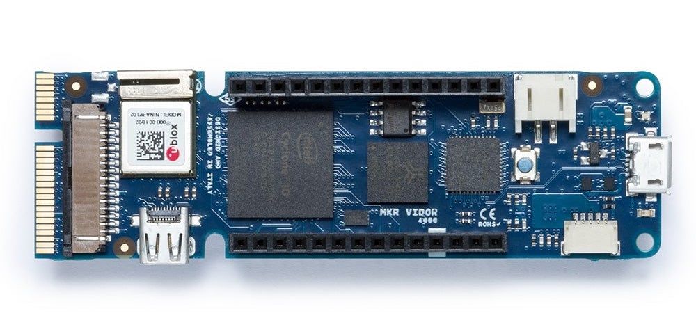
This Arduino is especially interesting because it contains both an ARM Cortex-M0+ microcontroller and an Intel Cyclone FPGA. For this post we'll only be working with the microcontroller, but if you're interested in the FPGA, check out our post on professional video with Arduinos.
The microcontroller is an ATSAMD21G18A. Its data sheet will be our primary API reference. The Cortex-M0+ Generic User Guide will also be useful here. According to the data sheet:
After reset has been released, the CPU starts fetching PC and SP values from the reset address, which is 0x00000000.
And the Cortex user guide says more specifically:
On reset, the processor loads the MSP with the value from address 0x00000000.
On reset, the processor loads the PC with the value of the reset vector, that is at address 0x00000004.
So all we have to do is...
- Put our program in the microcontroller's flash memory.
- Put a pointer to the stack at address 0x00000000.
- Put a pointer to our program at address 0x00000004.
Flashing
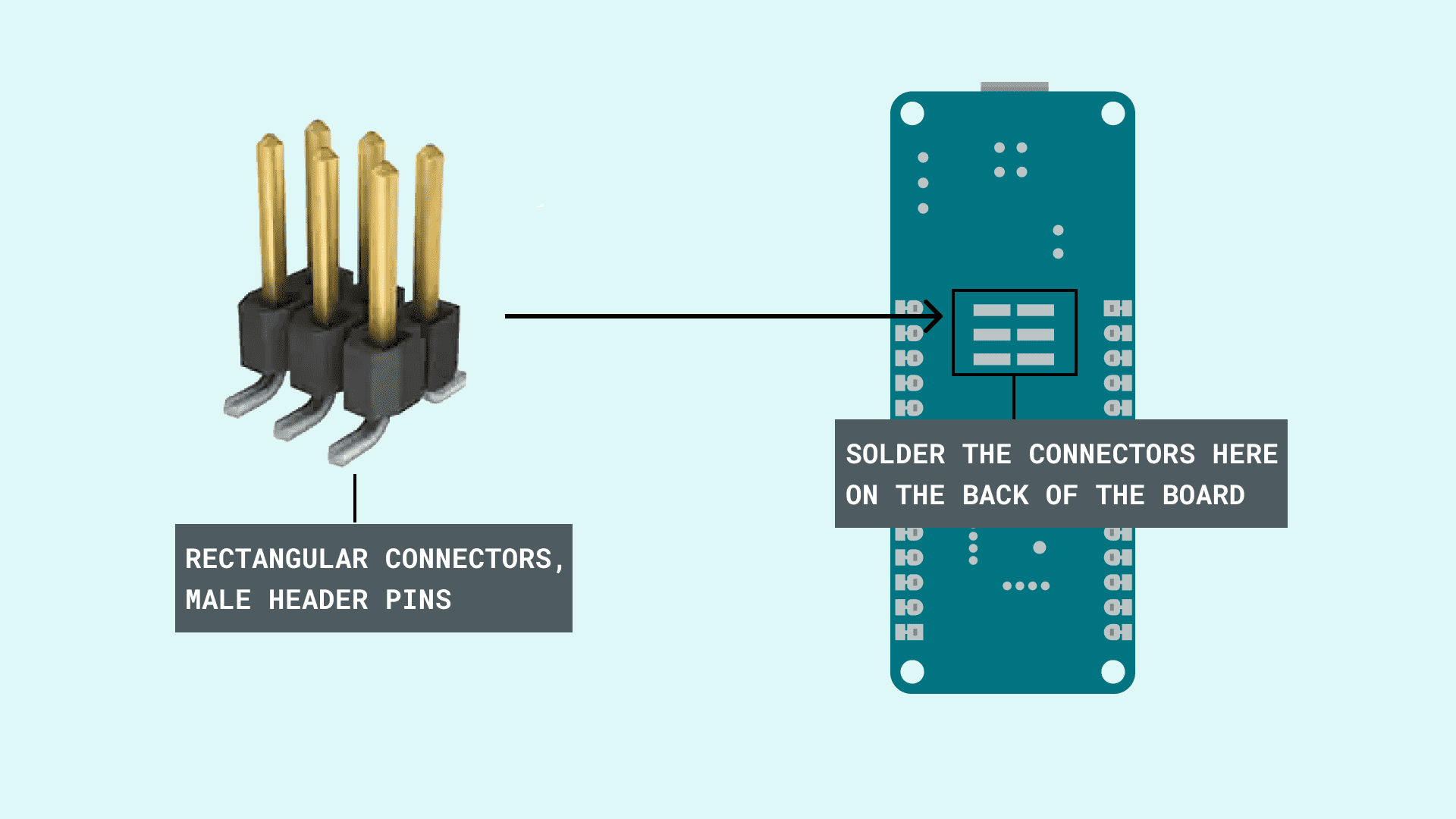
How does code get on the chip to begin with? According to the data sheet, it's done using two-pin Serial Wire Debug (SWD) programming. To program it using the SWD interface, we need to grab a debugger and physically connect it to the chip. There are exposed pads on the Arduino MKR boards that can be used for this if you're willing to solder or rig up a device to hold the wires against them:
But that would be a pain, and Arduinos are typically programmed via USB. This is enabled by the Arduino bootloader.
A bootloader is often the first thing you'd want to put on a microcontroller since its main job is to make programming the device easier. Arduinos come with a pre-installed bootloader that allows the device's memory to be read or written via USB and the SAM-BA protocol if the user double taps the reset button. Otherwise, it'll jump to the code at address 0x00002000.
Assuming our microcontroller has this bootloader pre-installed, our new goal is:
- Put our program in the microcontroller's flash memory.
- Put a pointer to the stack at address 0x00002000.
- Put a pointer to our program at address 0x00002004.
And we can do that by double tapping the reset button, then using the SAM-BA protocol to manipulate the memory.
The Program
We don't get a kernel to interface with. That means no processes, no threads, no filesystem, no networking, and so on. We can't use the Rust standard library at all. And we can't use the usual main entry point as we just have to put our entry point in the right place. If we stub out our hello world program taking those things into consideration, it looks like this:
#![no_std]
#![no_main]

fn enable_led() {
    unimplemented!()
}

fn turn_led_on() {
    unimplemented!()
}

fn turn_led_off() {
    unimplemented!()
}

fn delay() {
    unimplemented!()
}

fn run() -> ! {
    enable_led();
    loop {
        turn_led_on();
        delay();
        turn_led_off();
        delay();
    }
}
And to make this compile, we also have to define a panic handler:
#[panic_handler]
fn panic_handler(_info: &core::panic::PanicInfo) -> ! {
    // there's not a whole lot we could do here right now...
    loop {}
}
The first stub is enable_led. The Arduino we're using has an LED built into the board attached to pin "PB08". Before we can control it, we need to configure it to be an output. Like every other interaction we'll have with the microcontroller, this is done by writing to a register at a predefined memory location. Specifically, to control the pins of the microcontroller, we need to write to the registers for the "PORT" peripheral. The SAMD21 defines the registers and address for PORT like so:
#[repr(C)]
pub struct PortGroup {
    pub data_direction: u32,
    pub data_direction_clear: u32,
    pub data_direction_set: u32,
    pub data_direction_toggle: u32,
    pub data_output_value: u32,
    pub data_output_value_clear: u32,
    pub data_output_value_set: u32,
    pub data_output_value_toggle: u32,
    pub data_input_value: u32,
    pub control: u32,
    pub write_configuration: u32,
    pub reserved_0: [u8; 4],
    pub peripheral_multiplexing: [u8; 16],
    pub pin_configuration: [u8; 32],
    pub reserved_1: [u8; 32],
}

#[repr(C)]
pub struct Port {
    pub groups: [PortGroup; 2],
}

const PORT_ADDRESS: u32 = 0x41004400;
Pins are divided into two groups (A and B), so to configure PB08 to be an output, we write to the registers using core::ptr::write_volatile (In lieu of the standard library, we get the Rust core library.):
unsafe fn enable_led() {
    let port = &mut *(PORT_ADDRESS as *mut Port);
    write_volatile(&mut port.groups[1].pin_configuration[8], 0b00000010);
    write_volatile(&mut port.groups[1].data_direction_set, 1 << 8);
}
Enabling and disabling the LED are also done with writes to these registers:
unsafe fn turn_led_on() {
    let port = &mut *(PORT_ADDRESS as *mut Port);
    write_volatile(
        &mut port.groups[1].data_output_value_clear as *mut u32,
        1 << 8,
    )
}

unsafe fn turn_led_off() {
    let port = &mut *(PORT_ADDRESS as *mut Port);
    write_volatile(
        &mut port.groups[1].data_output_value_set as *mut u32,
        1 << 8,
    )
}And finally, to implement a delay...
unsafe fn delay() {
    for i in 0..100000 {
        read_volatile(&i);
    }
}
It's just a busy loop. But since we're running on a microcontroller, it's an incredibly predictable busy loop. Once compiled, it'll always take exactly the same amount of time to execute.
Memory Layout
We need a pointer to our code to be at a very specific address (0x00002004). We also need to put a stack pointer at a very specific address (0x00002000). These addresses are actually part of a larger list of pointers known as the exception table:
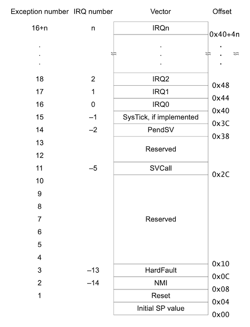
In code, this looks like this:
pub type Handler = unsafe extern "C" fn();

#[repr(C, packed)]
pub struct ExceptionTable {
    pub initial_stack: *const u32,
    pub reset: unsafe extern "C" fn() -> !,
    pub nmi: Handler,
    pub hard_fault: unsafe extern "C" fn() -> !,
    pub reserved_0: [Option<Handler>; 7],
    pub sv_call: Handler,
    pub reserved_1: [Option<Handler>; 2],
    pub pend_sv: Handler,
    pub sys_tick: Option<Handler>,
    pub external: [Option<Handler>; 32],
}
We don't need to define any of these except the reset handler and the initial stack pointer, which points to the end of the chip's RAM:
unsafe extern "C" fn reset_handler() -> ! {
    run()
}

unsafe extern "C" fn nop_handler() {}

unsafe extern "C" fn trap() -> ! {
    loop {}
}

#[link_section = ".isr_vector"]
pub static ISR_VECTORS: ExceptionTable = ExceptionTable {
    initial_stack: 0x20008000 as _,
    reset: reset_handler,
    nmi: nop_handler,
    hard_fault: trap,
    reserved_0: [None; 7],
    sv_call: nop_handler,
    reserved_1: [None; 2],
    pend_sv: nop_handler,
    sys_tick: None,
    external: [None; 32],
};
Now we just need to tell the linker to place the section we've designated ".isr_vector" at address 0x00002000. This is done using a linker script:
MEMORY
{
    FLASH_FPGA (r) : ORIGIN = 0x40000, LENGTH = 2M
    FLASH (rx) : ORIGIN = 0x2000, LENGTH = 0x00040000-0x2000 /* first 8KB used by bootloader */
    RAM (rwx) : ORIGIN = 0x20000000, LENGTH = 0x00008000
}

ENTRY(reset_handler)

SECTIONS
{
    .text :
    {
        . = ALIGN(0x2000);
        KEEP(*(.isr_vector))
        *(.text*)
    } > FLASH

    /DISCARD/ : {
        *(.ARM.exidx .ARM.exidx.*);
    }
}
This file can be given to the linker to tell it how to lay out everything.
Running
You can build your program with Cargo by passing in the target and linker script like so:
RUSTFLAGS="-Clink-arg=-Tlayout.ld" cargo build --target thumbv6m-none-eabiAfter installing the ARM embedded toolchain, you can convert that from an ELF executable to a binary that you can flash your microcontroller with:
arm-none-eabi-objcopy -O binary target/thumbv6m-none-eabi/debug/hello-microcontroller program.binAnd finally, if you double tap your Arduino's reset button, you can flash it with BOSSA:
bossac -i -d --port /dev/cu.usbmodem* -o 0x2000 -e -o 0x2000 -w program.bin -R
Next Steps
- Check out the code from our GitHub repository and run it yourself.
- Check out some of the awesome embedded Rust resources.
- If you're interested in building elegant, bespoke hardware, download the schematics for an Arduino and build a custom PCB.
- If you like working on this sort of thing, come join us at Tempus Ex and get paid to build cool stuff with Rust.