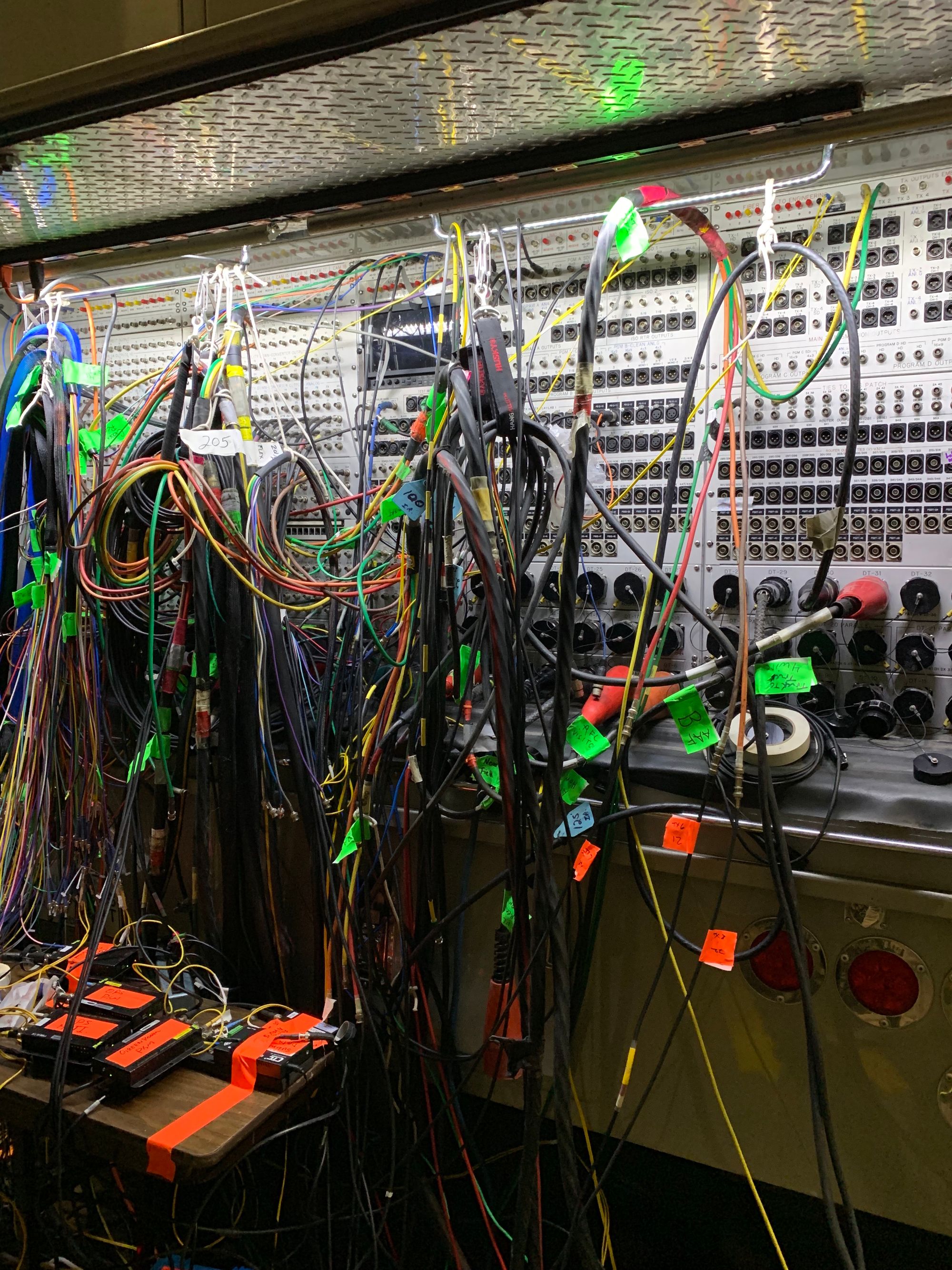
In the world of professional video, SDI (Serial Digital Interface) is the industry standard for getting video from point A to point B. It's the professional's equivalent of HDMI for consumer electronics. At any large-scale, televised event, you can bet that somewhere behind the scenes, there's a rat's nest where all of the video comes together and is distributed via SDI. In this post, we'll do a deep dive into SDI, then create what's possibly the world's cheapest SDI signal generator by fabricating an SDI transmitter for an Arduino.
SDI Deep Dive
One of the strong suits of SDI is that it's very simple. This "deep dive" should be followable for those that have no prior knowledge of SDI, and after reading this, you'll know more or less everything there is to know.
SDI signals are one-way signals transmitted via a coaxial cable. The signals are transmitted at a constant bit rate depending on what SDI standard is used. There are several standards, such as HD-SDI, 3G-SDI, 6G-SDI, and 12G-SDI, where the primary differences are the supported bitrates. For example, HD-SDI supports two bitrates: 1.485 and 1.485/1.001 Gbps.
The data transmitted consists of the video's raw pixels as luminosity and color samples (in 4:2:2 YCbCr format), some markers, and some padding to make sure the data stream matches one of the supported bitrates. The pixels form the "active picture" and the padding is known as the horizontal and vertical "blanking intervals":

The above regions are transmitted in order from top to bottom and left to right as 10-bit words, with an "EAV" (End of Active Video) marker coming in each row before the horizontal blanking and an "SAV" (Start of Active Video) marker coming after the horizontal blanking. These markers also contain 2 flags: one to indicate if the current row is in the vertical blanking interval, and one to indicate for interlaced video whether the picture is field one or field two. Receivers can use these markers to determine the resolution, frame rate, and content of the video.
Now you know more or less everything there is to know about the SDI standard.
Putting It Into Practice
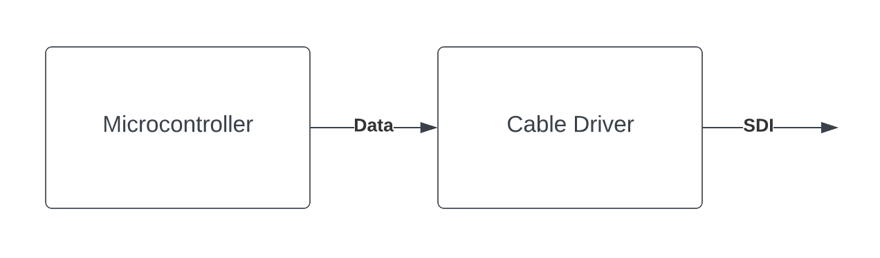
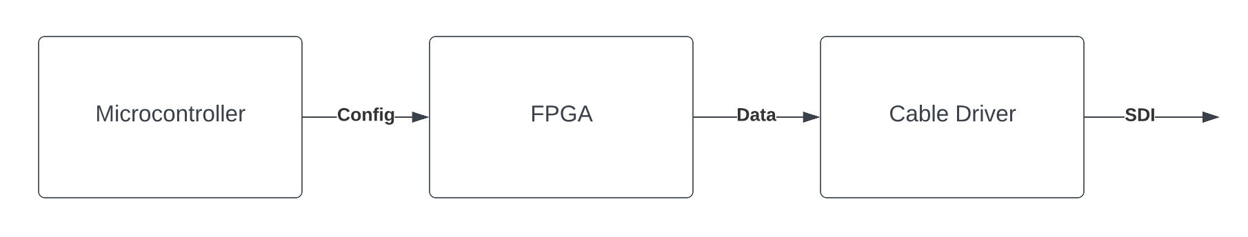
We're going to build the "hello world" of SDI hardware: a signal generator. This will be a device that outputs some arbitrary signal over an SDI output. To keep it simple, we'll just make the signal some flashing colors. And we'll aim to make this a 1080p30 signal, which can be transmitted via HD-SDI. In theory, we just need to program a microcontroller that can send a 1.485 Gbps signal to a cable driver:
This would work if we could get our hands on such a microcontroller, but 1.485 Gbps is quite fast. To be able to generate a signal at that speed, we'll need an FPGA, which can be programmed using a lower-level hardware description language to perform much faster operations. In Hello, Microcontroller, I demonstrated running Rust code on the Arduino MKR Vidor 4000:
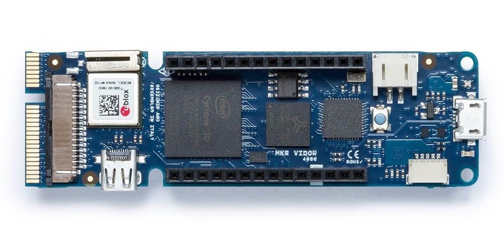
This Arduino is unique because it contains both a microcontroller and an Intel Cyclone 10 FPGA. Maybe we can use that to do the heavy lifting:
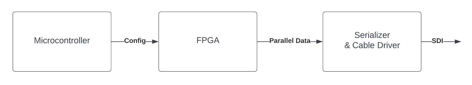
This is frequently how professional-grade SDI hardware is actually implemented, but there's still a catch: The Cyclone 10 FPGA on the MKR Vidor 4000 can't transmit a 1.485 Gbps signal either; its pins max out at around 200 MHz. Luckily, that's fast enough to use an external serializer, such as the Semtech GS2962. We'll send our data to the external serializer using 10 parallel data lines, each operating at 148.5 Mbps. The Semtech GS2962 also has an integrated cable driver, so once it gets the parallel data signal, it can do all the rest:
Actualization
To make the signal generator real, a PCB needs to be designed. The MKR Video 4000 exposes most of its FPGA pins via the MiniPCI Express connector on the end, so the PCB will need to fit onto that.
Designing a PCB may be intimidating if you've never done it, but here's a little secret: Manufacturers of circuit components write insanely thorough documentation. If you look through the datasheet for an integrated circuit, you'll almost always find diagrams and tips for typical applications and PCB placement. As a result, PCB design is largely an exercise in just following instructions.
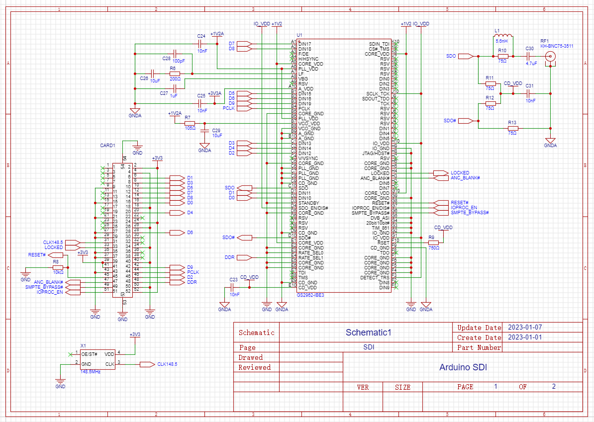
After a thorough read of the instructions, the next step is to create a schematic, which connects the Semtech serializer to a MiniPCI connector and SDI connector:
With a schematic completed, the physical design step is next. For boards like this, a 4-layer PCB "stack-up" is common. On the top and bottom of our PCB will be two signal layers, and sandwiched in the middle of the PCB, there will be two ground layers. We'll arrange all our components on the top of the PCB, taking into consideration guidance from the manufacturer datasheets, the proximity of related components, and signal / current pathing.

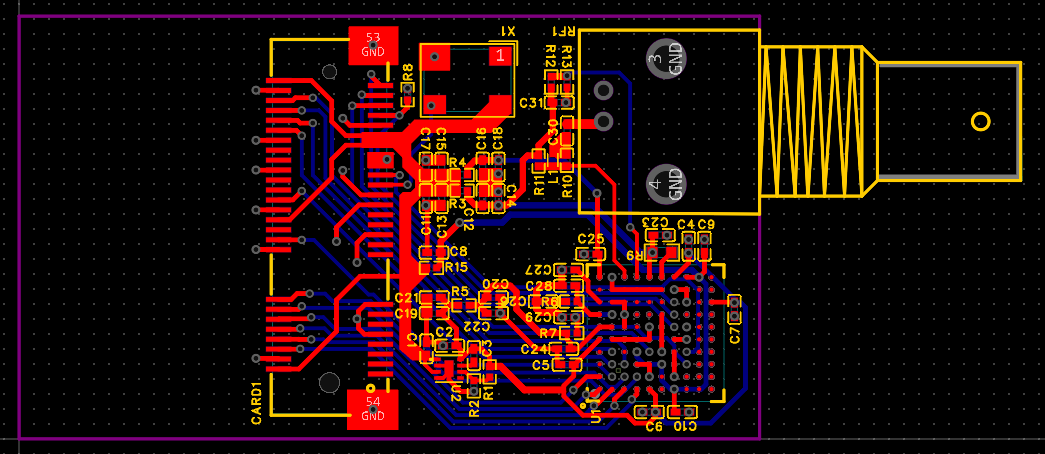
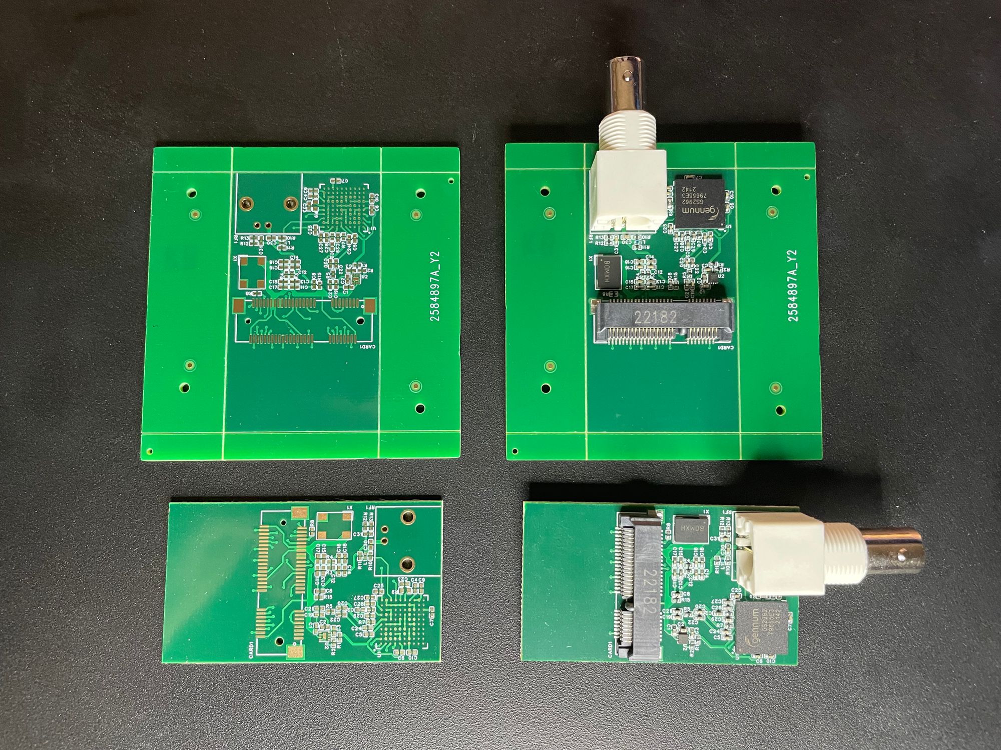
Once the PCB is physically laid out, the design can be sent to a PCB assembly service and once produced, looks like this:
Programming
The FPGA now needs to be programmed to emit a signal. Starting with the template in github.com/vidor-libraries/VidorFPGA, some Verilog will need to be written to interface with the serializer.
Many of the connections are hard-wired high or low and the rest forward the clock and parallel data to the serializer:
assign wCLK1485 = iPEX_PIN31;

reg [9:0] data;

assign bPEX_PIN45 = 1; // reset disable
assign bPEX_PIN47 = 0; // anc blanking
assign bPEX_PIN49 = 1; // smpte mode
assign bPEX_PIN51 = 1; // io processing
assign bPEX_PIN44 = wCLK1485;
assign bPEX_PIN48 = 0; // not ddr
assign bPEX_PIN16 = data[0];
assign bPEX_PIN6  = data[1];
assign bPEX_PIN46 = data[2];
assign bPEX_PIN8  = data[3];
assign bPEX_PIN20 = data[4];
assign bPEX_PIN10 = data[5];
assign bPEX_PIN28 = data[6];
assign bPEX_PIN12 = data[7];
assign bPEX_PIN14 = data[8];
assign bPEX_PIN42 = data[9];
Now, the correct parallel data just needs to be placed in the data register at the right time. To do that, some math needs to be done:
- We're going to output 1080p video at 30 frames per second.
- To pad this to 1.485 Gbps, this will be transmitted as 1125 lines per frame, with each line consisting of 4400 words.
- Each line will consist of two interleaved streams: one for luma samples and one for chroma samples.
- In each line, each of those two interleaved streams will consist of 4 EAV words, 272 blanking words, 4 SAV words, and 1920 words for the active picture, totaling 2200 10-bit words.
- Self-check: (4+272+4+1920)*2*1125*30*10 = 1.485 Gbps
If we just maintain a few counters, we can update the data register based on a simple case statement:
reg [15:0] frame_counter; // counts indefinitely
reg [11:0] line_counter; // counts from 0 to 1124
reg [15:0] line_word_counter; // counts from 0 to 4399
// The serializer reads data on the positive PCLK edge, so we'll do our updates on the negative edge.
always @(negedge wCLK1485) begin
case (line_word_counter)
12'd0, 12'd1, 12'd552, 12'd553:
// SAV/EAV word 0
data<=10'h3ff;
12'd2, 12'd3, 12'd4, 12'd5, 12'd554, 12'd555, 12'd556, 12'd557:
// SAV/EAV word 1/2
data<=10'h0;
12'd6, 12'd7:
// EAV word 3
data<=line_counter < 12'd1080 ? 10'b1001110100 : 10'b1011011000;
12'd558, 12'd559:
// SAV word 3
data<=line_counter < 12'd1080 ? 10'b1000000000 : 10'b1010101100;
default:
// Blanking interval or active picture. If this is the blanking interval, the value here is ignored by the serializer since we set ANC_BLANK to low.
// The luma will be constant, but we'll toggle the chroma with the LED.
data<=line_word_counter[0] ? 10'h200 : (frame_counter[5] ? 10'h80 : 10'h37f);
endcase
// Tick up counters.
if (line_word_counter==16'd4399) begin
line_word_counter<=16'h0;
if (line_counter==12'd1124) begin
line_counter<=12'h0;
frame_counter<=frame_counter+16'h1;
end else begin
line_counter<=line_counter+12'h1;
end;
end else begin
line_word_counter<=line_word_counter+16'h1;
end
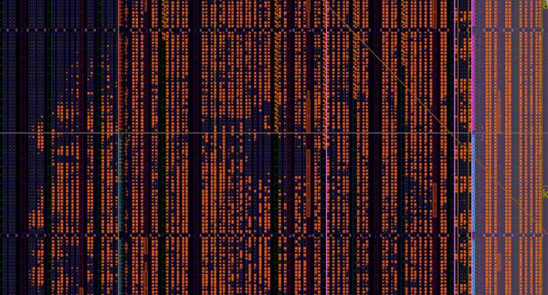
endResult
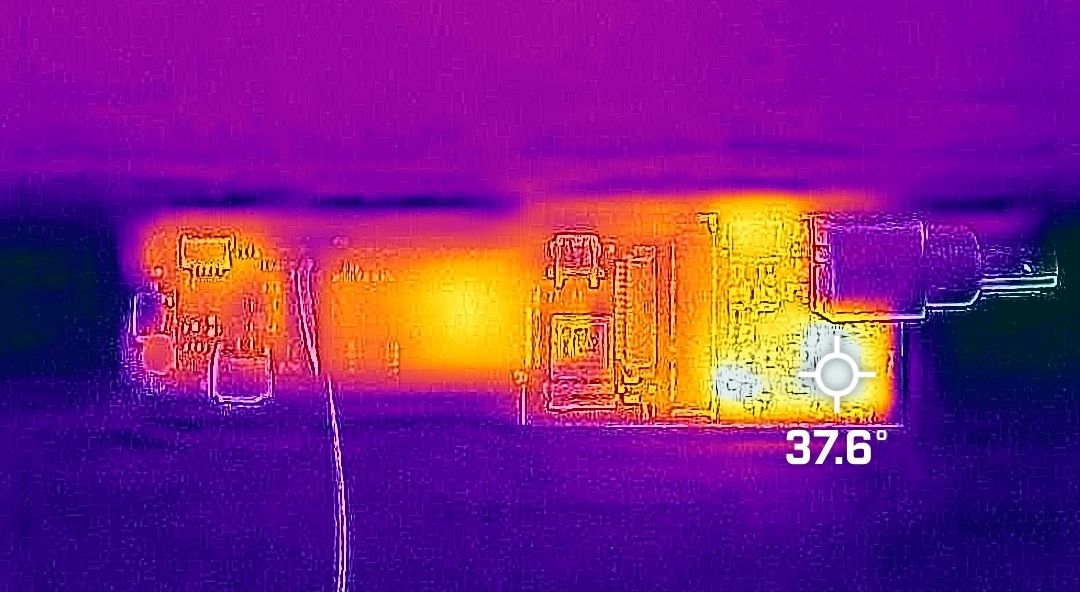
When testing PCBs for the first time, the first check I like to do is with a thermal camera. If a PCB assembly service bridged a pad they shouldn't have, resulting in a short, a thermal camera can tell you very quickly and to some extent tell you where the short is. In this case, the hottest component is the serializer, and it stabilizes around 37.6ºC, well under the max of 85ºC.
And once the code is uploaded to the device:
As far as I know, this is the first time an Arduino has been capable of generating and emitting arbitrary SDI video signals, and as far as I know, this is also the cheapest SDI signal generator available anywhere. SDI signal generators typically cost anywhere from $350 to $2,000. This one costs ~$87 for the Arduino and ~$95 for the transmitter parts and assembly at low volumes.
Although I don't recommend using an Arduino like this in mission critical workflows, it can be a valuable tool in the lab.
If you'd like to see the files or build this yourself, you can find the schematics and project files at github.com/tempus-ex/arduino-sdi.
And if you'd like to get closer to this kind of tech, check out the openings we have available at Tempus Ex.